cadnano/
cadnano paper figure 1 draft
2008-11-04Attachments:
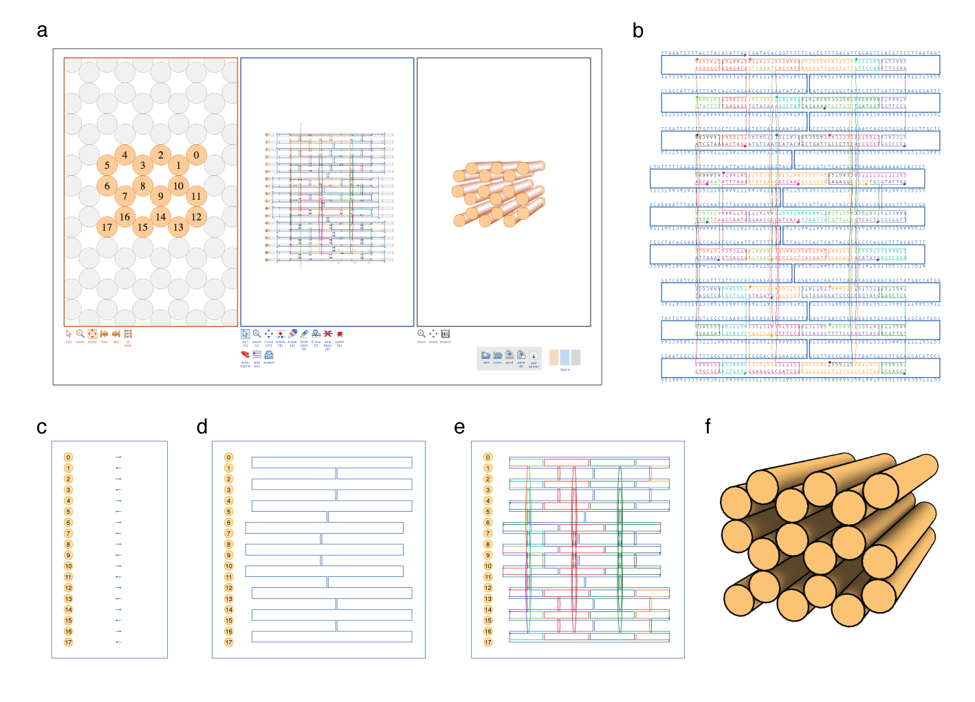
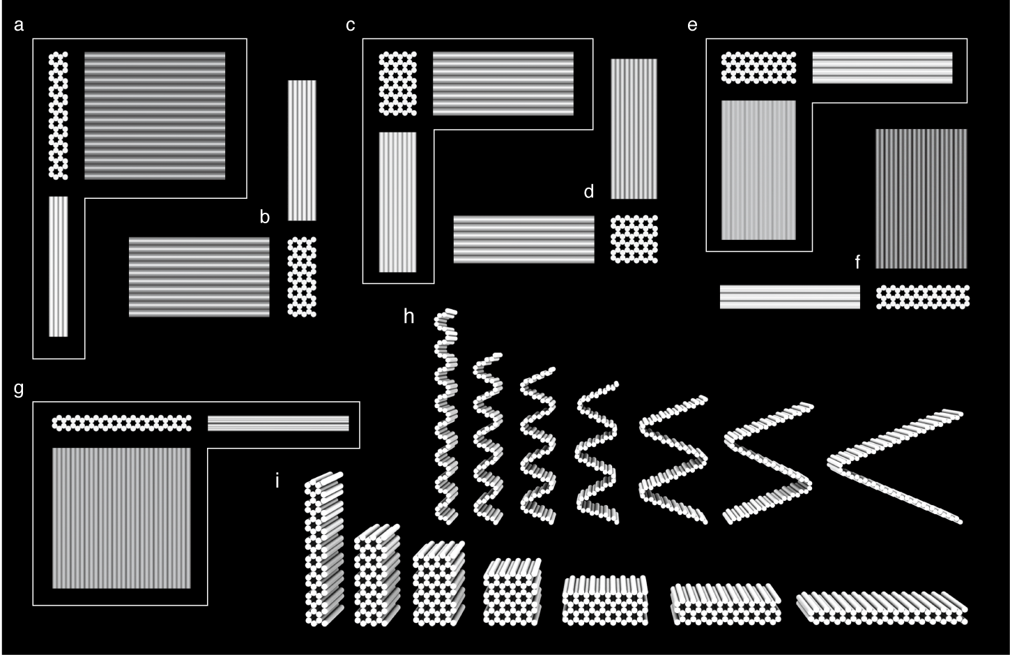
Figure 1 draft

Figure 1 | Designing 3D DNA origami shapes with caDNAno. a, Screenshot of caDNAno interface. Leftmost Slice panel displays a cross-sectional view of the honeycomb lattice where helices can be added to the design. The center Path panel provides an interface to edit an unrolled 2D schematic of the scaffold and staple paths. The rightmost Render panel provides a real-time 3D model of the design. b, Exported SVG schematic of example design from a, with scaffold (blue) and staple (multi-color) sequences. c, Path panel snapshot during first step of the design process. Short stretches of scaffold are inserted into the Path panel as helices are added via the Slice panel. d, The Path panel editing tools are used to stitch together a continuous scaffold path. e, The auto-staple button is used to generate a default set of continuous staple paths, including crossovers. The breakpoint tool is subsequently used to split the staple paths into lengths between 18 and 49 bases. Finally, the scaffold sequence is applied (as in b) to generate the list of staple sequences. f, Exported X3D model from the Render panel.
Figure 2 draft
- Move gel to figure 3

Figure 2 | Designs of honeycomb DNA origami blocks.. a, b, c, d, e, f, g, h, Unrolled conceptual intermediate showing scaffold connectivity of each design. i, Perspective view of 3D models of shapes a–g.